Design Services
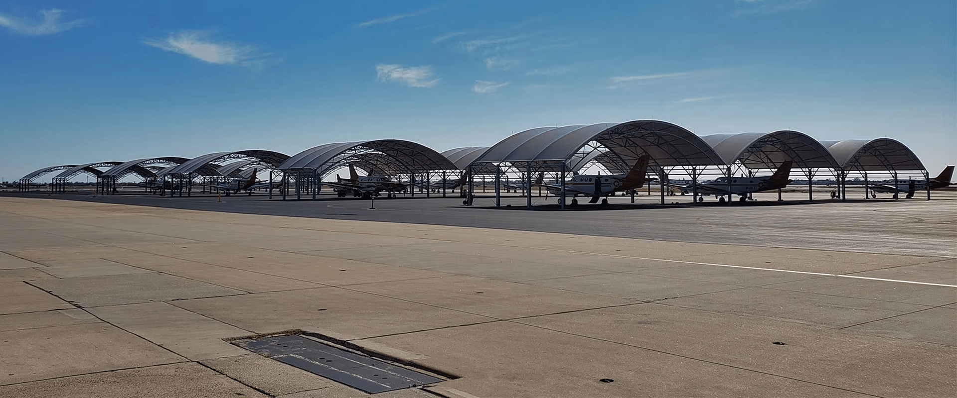
Drainage Design for Multi-Unit Umbrella Tensile Roofs
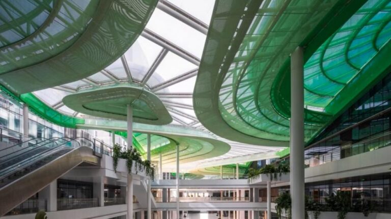
With their lightweight, fluid, and curvilinear forms, tensioned membrane structures have become a preferred choice for shading and rain protection in public plazas, transit hubs, and open-air gathering areas. The accompanying photographs showcase a large-scale membrane roof composed of multiple independent, umbrella-shaped units. Featuring a structured grid layout and radial segmentation, the design balances spatial aesthetics with structural logic. However, the primary challenge in realizing such a form lies in developing a systematic drainage strategy.
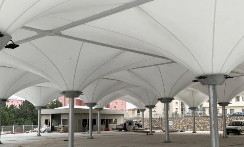
Unlike rigid roofing, membrane materials are highly flexible. Any oversight in drainage design can easily lead to water ponding—a phenomenon that triggers a vicious cycle: rainwater causes the membrane to sag, creating a depression that collects even more water. As the load increases, it can ultimately result in critical safety issues, such as the tearing of the membrane or the failure of structural connections—a phenomenon often referred to in the industry as the “Matthew effect of water ponding.” For interconnected, umbrella-style membrane assemblies, designers cannot focus solely on visual uniformity; they must integrate drainage logic into the curved geometry during the initial form-finding phase.

This project employs a drainage strategy based on high points at each unit and collection channels (valleys) between them. Each umbrella-shaped unit features a high point at the top of a central support column, with the membrane extending radially outward to form a doubly-curved conical surface that naturally slopes downward. Rainwater flows along the radial seams toward the low-lying valleys between the units. As the umbrella units are arranged in an orderly fashion, they create continuous drainage channels; rainwater is directed along these valleys rather than flowing haphazardly across the membrane surface. This gravity-driven flow—achieved through the curvature of the surface—represents the most economical and effective fundamental principle for drainage in tensioned membrane structures. During the form-finding process, it is essential to ensure that sufficient slope is maintained across the entire membrane surface, avoiding near-horizontal “dead zones” where water could stagnate.

The valley junctions between the units serve as the critical nodes for the entire drainage system. In conventional, standalone umbrella-like membrane structures, rainwater typically drains via unorganized runoff, dripping directly from the edges. However, given the large coverage area of this project—which features a continuous circulation space underneath—such unorganized runoff would create localized “curtains” of falling water, negatively impacting the user experience. To address this, continuous water-guiding elements are integrated along the valley lines where the membrane units connect. These elements collect dispersed rainwater and channel it toward designated drainage points, transforming the runoff into an organized drainage system. Furthermore, the radial seams on the membrane surface function as ridges for water guidance; the raised seams act as subtle channels that direct the flow of rainwater, preventing lateral overflow and reducing the risk of leakage.

Controlling pre-tension is essential for maintaining a stable drainage geometry. Because the slope of a flexible membrane surface is not static, precise control of pre-tension during installation is required to ensure that the membrane does not undergo excessive deformation under its own weight or the load of accumulated rainwater. If the tension is insufficient, localized sagging may occur after rainfall, compromising the intended drainage slopes and creating new areas for water ponding. In large-scale, interconnected umbrella membrane structures, the tension applied at the apex and edge-restraint nodes of each unit must be carefully balanced. This ensures consistent surface geometry across all units, smooth transitions along the valley lines, and an uninterrupted flow path, preventing localized misalignments or obstructions to water runoff.

Regarding construction details, waterproofing at the nodes and overflow protection are critical. Water-collection hoppers and connection nodes along the valley lines are equipped with sealed, waterproof assemblies to prevent leakage through gaps. Additionally, an overflow system is incorporated to handle extreme weather events; should a drainage outlet become temporarily blocked or the volume of rainfall exceed the design capacity, the overflow channels provide an emergency release, safeguarding the structural integrity of the entire system. Once collected, the rainwater is directed into the site’s municipal storm-drainage network via downspouts. This creates a closed-loop drainage system, keeping the space below dry and preventing rainwater from spreading or pooling on the ground.

From an aesthetic perspective, the advantage of this umbrella-like grid membrane structure lies in the seamless integration of the drainage system with the architectural form; there are no intrusive external gutters to disrupt the clean, curvilinear appearance. This demonstrates that superior membrane structure design does not prioritize form at the expense of drainage; rather, it allows the logic of drainage to dictate the shaping of the curved surfaces. By employing a strategy that combines high points within each unit, valley lines for water collection, pre-tensioning for shape control, and integrated node-based drainage, the design preserves the light, airy, and artistic quality of the tensile membrane while effectively addressing the drainage challenges inherent in large-span, interconnected membrane roofs. This approach is exceptionally well-suited for expansive open spaces such as public transport hubs, community plazas, and open-air markets.

In summary, for multi-unit, umbrella-like tensile membrane structures, drainage is a core consideration that informs every stage of the process—from initial conceptualization and form-finding to fabrication and tensioning. Only by holistically designing the surface geometry, slopes, pre-tension, node-based water routing, and overflow protection can one achieve a balance between aesthetics, safety, and functional utility—ensuring that the tensile membrane not only provides shelter from the sun and rain but also remains resilient against rainfall of varying intensities.