Design Services



How to Reduce Wrinkles in Tensile Membrane Structures
As a modern architectural form, membrane structures have seen rapid development and widespread application both internationally and domestically. Examples include sports facilities (stadiums, arenas, natatoriums, fitness centers, tennis and basketball halls); cultural facilities (exhibition centers, theaters, conference halls, museums, botanical gardens, and aquariums); transportation infrastructure (airports, railway stations, bus terminals, toll plazas, piers, gas stations, and pedestrian overpasses); commercial facilities (malls, shopping centers, hotels, restaurants, storefront canopies, and commercial streets); industrial facilities (factories, warehouses, research centers, processing facilities, greenhouses, and logistics hubs); and landscape features (building entrances, landmark installations, pedestrian zones, and parking areas).
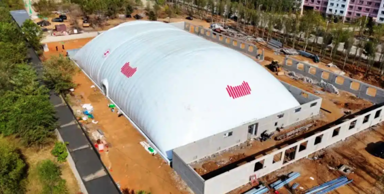
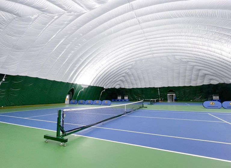
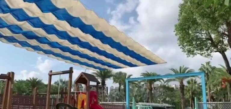
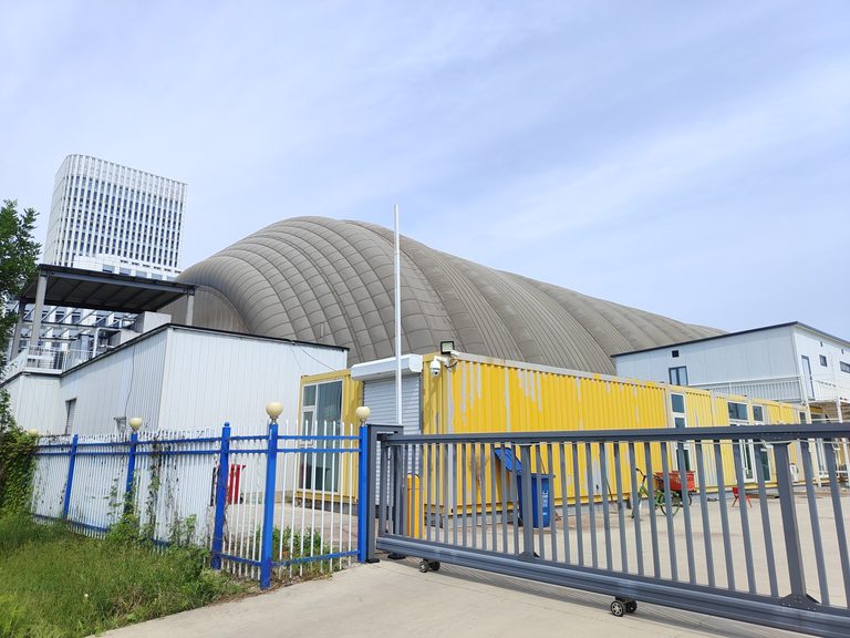
The versatility of membrane structures across these diverse sectors stems from their unique architectural characteristics. Based on their structural configuration, membrane structures are categorized into frame-supported, tensioned, and pneumatic types—all of which offer immense design flexibility. However, a common issue encountered in completed projects is the appearance of wrinkles on the membrane surface, which significantly detracts from the structure’s aesthetic appeal. This article analyzes the causes of such wrinkling—covering material selection, fabrication, and construction—and offers recommendations for mitigation.
I. Reducing Membrane Wrinkling Through Material Selection
The raw materials used in production dictate the properties of the final product. During the design phase, it is essential to evaluate the mechanical properties of the chosen materials to ensure they meet design specifications without causing structural deformation or damage.
1. PTFE-coated membrane material consists of an ultra-fine fiberglass fabric coated with polytetrafluoroethylene (PTFE) resin. This material offers excellent weldability, superior resistance to ultraviolet (UV) radiation and aging, and high flame retardancy. However, due to the inherent brittleness of the fiberglass substrate, its mechanical properties can be affected by moisture and heat. Under the influence of tensile forces and ultraviolet (UV) radiation, the material is prone to significant creep, which often leads to the formation of wrinkles on the membrane surface. Consequently, the use of PTFE-coated fiberglass membranes is generally reserved for indoor applications or environments with controlled, favorable conditions.
2. PVC architectural membrane materials were developed and applied relatively early. Standards typically require that the thickness of the PVC coating at the intersections of the warp and weft yarns of the fiberglass fabric be no less than 0.2 mm; the coating is generally kept to the minimum thickness necessary to meet functional requirements. As PVC itself lacks long-term aging resistance, it is primarily used for temporary structures.
3. ETFE architectural membrane material is manufactured directly from ETFE (ethylene-tetrafluoroethylene copolymer) resin. ETFE offers excellent impact resistance, electrical properties, thermal stability, and chemical resistance, combined with high mechanical strength and good processability. In recent years, ETFE membranes have demonstrated significant advantages and strong market potential, often serving as a superior alternative to other materials. Known as “soft glass,” this membrane features exceptional light transmission and is extremely lightweight—weighing only 1% as much as an equivalent pane of glass. It possesses high toughness, high tensile strength, and high tear resistance, with an elongation at break exceeding 400%. It exhibits excellent weatherability and chemical resistance, with a melting point as high as 200°C. Furthermore, it enables the effective use of natural light (contributing to energy savings) and offers good acoustic performance. ETFE membranes are suitable for a wide variety of architectural membrane structures.

II. Minimizing Membrane Surface Wrinkles through Structural Fabrication
Structural fabrication encompasses both the supporting structure and the membrane surface itself. The supporting structure is typically made of steel, and the fabrication process involves the following steps: material cutting; layout according to design drawings; construction of jigs/molds; bending of components; assembly of arched members; determination of segment divisions; tack-welding of support members at connection nodes; welding of side A; inspection of weld quality; turning over of segments; welding of side B; inspection of weld quality; on-site assembly; application of the topcoat; and final inspection of weld quality. 1. Reducing Membrane Wrinkling through Steel Structure Fabrication
Cutting: After the materials undergo shot-blasting for rust removal, they are cut using an intersecting-profile cutting machine. The cut edges are then cleaned of slag and debris in preparation for assembly. All cut structural members must be beveled. For materials used at reinforced joints, in addition to cutting to the required length, they are also slit along the axial direction to facilitate installation.
Layout (Lofting): Layout must be performed strictly in accordance with the engineering drawings. Care should be taken during this process, which is carried out on a prepared jig base.
Jig Preparation: The jig is constructed from 16mm-thick steel plates, with a width matched to that of the steel pipes. To conserve steel, two rows of plates can be joined together using channel steel for support. The assembly of curved pipes requires steel pipes with sufficiently large diameters and wall thicknesses (e.g., 12mm or 10mm). Welds at assembly points must meet Grade 1 quality standards; the root gap should be 2–4 mm, and the bevel angle 40 degrees. Backing pipes (sleeves) must be used at butt joints, regardless of whether the cross-sections are uniform or variable. Welding must be conducted in strict adherence to the established welding procedure. Each weld pass must be thoroughly cleaned to ensure the required Grade 1 weld quality.
Tack Welding: Before tack-welding the branch members, the layout markings for the joints are transferred onto the surfaces of the chord members. Tack welding is then performed according to the member identification numbers, generally proceeding from the center toward both ends. The spacing between tack welds should be approximately 50–100 mm, with each tack weld being 30 mm in length.
Welding: Welding must be carried out in strict compliance with the welding procedure specifications. For intersecting joints and butt joints, CO2 gas-shielded arc welding is preferred for the root pass, while manual welding may be used for the cover passes.
Weld Inspection: All butt welds are subject to inspection against Grade 1 weld standards; fillet welds that require beveling must also be inspected. In addition to a visual examination of the weld appearance, ultrasonic testing is required. Any welds found to be non-compliant must be repaired. On-site Splicing: During on-site splicing, a backing sleeve (insert) must be used at each joint. The entire truss should be leveled using temporary supports. Tools such as chain hoists (come-alongs) should be employed to align the weld seams precisely according to the design drawings; once aligned, the joints are tack-welded before the final, full-scale welding is performed. The supports must be of sufficient height to allow for all-around access for welding.
2. Reducing Membrane Wrinkling through Membrane Processing
Technical Preparation: Gather technical documentation and design the cutting and processing workflow for the membrane material.
Production Preparation: Develop procurement and production schedules based on the project’s bill of materials. All procured raw materials must be accompanied by product certificates of conformity. Furthermore, the quality inspection department must conduct random sampling and re-testing of these materials; only after they are confirmed to meet specifications can they be used for production and construction. As the membrane material is imported, this phase requires a relatively long lead time.
Production and Fabrication: Fabrication must strictly follow the cutting patterns generated by computer software, while accounting for the bi-directional elasticity of the membrane material. During cutting and composite processing, the material’s uniformity and integrity must be ensured—no defects are permitted. Membrane overlaps must be dimensioned correctly for high-frequency welding to ensure adequate tensile strength, with additional reinforcement applied at the overlap zones.
3. Reducing Membrane Wrinkling through Rigging Processing
Technical Preparation: Gather technical documentation, calculate the cutting lengths for the rigging components, and establish the corresponding fabrication processes.
Production Preparation: Develop procurement and production schedules based on the project’s bill of materials. All procured raw materials must be accompanied by product certificates of conformity and undergo random sampling and re-testing by the quality inspection department.
Testing and Inspection: Prior to fabrication, the wire ropes must undergo testing to verify their tensile strength and elastic modulus, ensuring they comply with relevant standards and confirming their material properties.
Fabrication: The processing of rigging components must meet strict precision requirements. This includes performing an initial pre-tensioning test during fabrication to ensure the components meet design specifications, followed by a final proof-load test upon completion to guarantee quality requirements are satisfied.
III. Reducing Wrinkles on the Membrane Surface During Structural Installation
Structural installation primarily involves the setup of the supporting framework and the installation of the membrane. The installation sequence is as follows: verifying steel frame dimensions—welding connection components—laying out the membrane and attaching hardware on the ground—folding the membrane—hoisting—unfolding—tensioning—positioning—adjusting.
1. Verifying Steel Frame Dimensions: Ensure that on-site machinery and equipment are safe, and verify that the center-to-center dimensions of the steel structure align with the specifications of the membrane model.
2. Welding Connection Components: Weld the connection components, remove welding slag, and grind down any weld beads or irregularities.
3. Laying Out the Membrane and Attaching Hardware: Unfold the membrane onto a clean, moisture-proof ground cover. Fold the membrane along its longitudinal axis, then secure it in a relaxed, free-hanging state. Temporarily position the membrane material, ensuring that all adjustment points remain accessible. Attach cables to the lower sections, insert edge ropes into the designated sleeves on the membrane, and secure the ropes at the membrane corners. Extend the cables toward the higher anchor points, ensuring they align with the connection points on the steel structure. Verify that all attachment pins meet design specifications, and confirm that all cables, equipment, and accessories are correctly positioned and secured.
4. Membrane Deployment: Hoist the membrane to its installation position and secure it firmly using cable clamps, while ensuring the fabric remains in a relaxed (slack) state. Extend the loose membrane and ridge cables toward the perimeter connection points; attach them to the perimeter connection plates and secure them firmly with cable clamps. Throughout this process, ensure the membrane remains in a relaxed state.
5. Positioning: Verify that all contact surfaces and connections within the steel-membrane structure are secure. Position the membrane in its designated location, ensuring proper alignment and structural stability. Once positioned, secure the membrane firmly using cable clamps, and finally, install the cover strips (clamping strips).
6. Adjustment: Perform final adjustments after the membrane is installed in its designated position. In actual production, the fabrication and installation of membrane structures are the primary factors contributing to the formation of wrinkles on the membrane surface. Consequently, those involved in construction should place greater emphasis on these two stages and implement robust, specific measures to minimize such wrinkles, thereby ensuring the aesthetic quality of the membrane structure.