Design Services



Air-Supported Structure Guide: 4 Key Selection Factors
Air-supported membrane structures differ significantly from traditional buildings in terms of construction logic and structural behavior. When selecting a structural system, it is essential to consider factors such as local wind and snow loads, intended function, and operational lifespan. This involves a comprehensive evaluation of the building’s plan geometry, rise-to-span ratio, cable system, and thermal insulation configuration—all while ensuring structural safety and meeting functional requirements, while simultaneously keeping overall costs under control.
Plan Geometry: Prioritize Simplicity and Symmetry
As wind-sensitive, flexible structures, air-supported membranes are directly influenced by their plan geometry, which dictates stress distribution across the membrane surface and the concentration of wind loads.
According to current Technical Specifications for Air-Supported Membrane Structures, the plan shape should ideally be simple and symmetrical—such as a rectangle, convex polygon, circle, ellipse, or a combination thereof. This ensures uniform structural loading, reduces peak local wind pressures, and enhances overall stability.
Designs should avoid sharp angles. Airflow around sharp corners can create vortices, leading to localized negative pressure and stress concentrations, which accelerate the aging and tearing of the membrane material.
Height of the Air-Supported Structure: Rise-to-Span Ratio
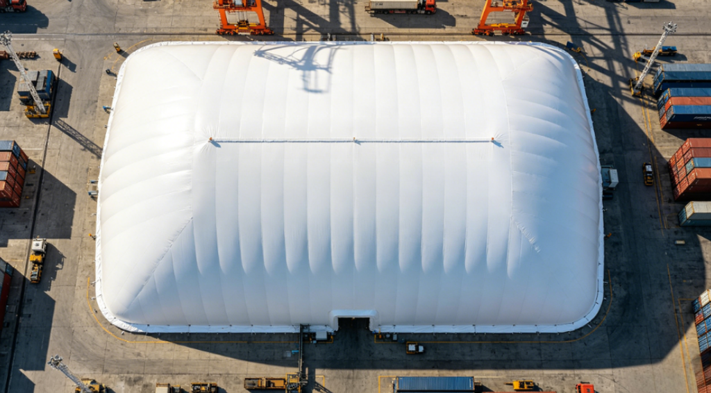
Regarding the height of an air-supported structure, current Technical Specifications for Air-Supported Membrane Structures recommend a rise-to-span ratio (the vertical height at the structure’s apex divided by its shorter span) between 1/3 and 2/3. In cases where there is no snow load, or where the roof is equipped with snow removal or melting systems, this ratio may be reduced, though it should not fall below 1/6.
Design strategies for the height of air-supported structures also vary depending on climatic conditions.
(1) Snowy Regions: Increasing Height
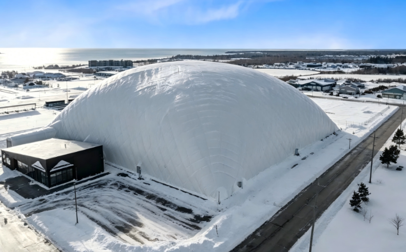
In cold, snowy regions, the rise of the structure can be increased, typically resulting in a rise-to-span ratio in the upper end of the 1/2 range. A steeper dome slope allows accumulated snow to slide off naturally under the force of gravity, thereby minimizing snow buildup on the membrane surface.
(2) Coastal regions prone to typhoons: Moderate reduction in rise
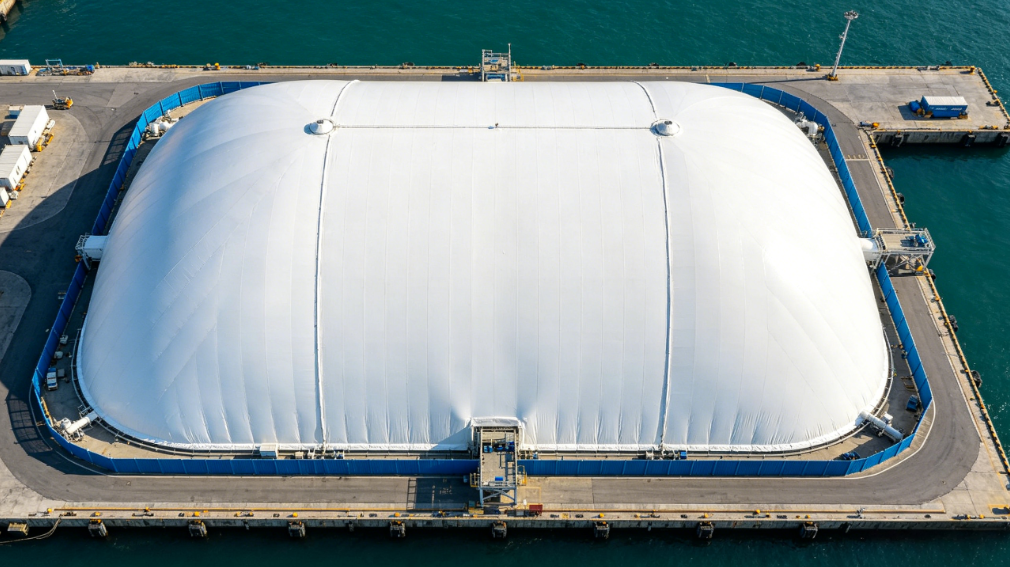
Provided that safety requirements are met, the rise of the dome for projects in typhoon-prone areas may be moderately reduced—with a rise-to-span ratio of no less than 1/4—to diminish the impact of strong winds on the structure.
Cable Systems: Configured based on wind-resistance requirements
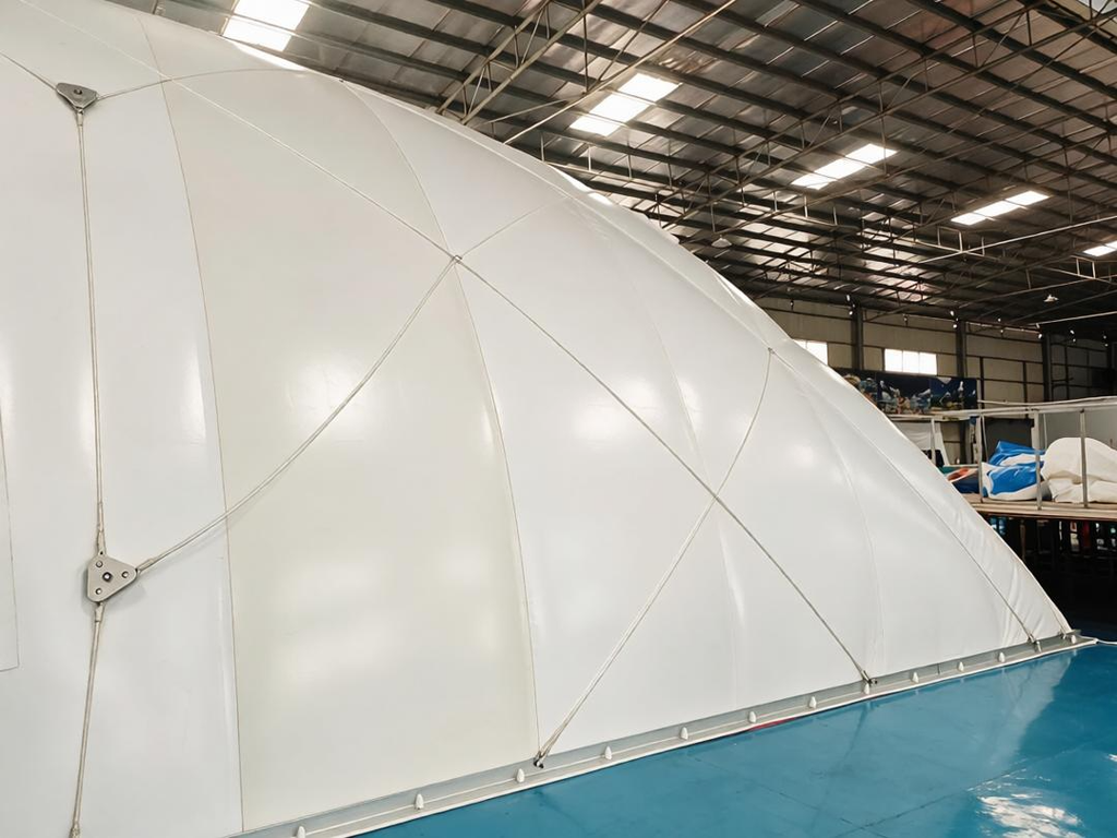
Cables (steel ropes) serve as the primary structural reinforcement for air-supported membranes to resist wind loads. Depending on the span, local wind pressure, and intended service life, projects can utilize various reinforcement configurations, such as unidirectional cables, orthogonal (grid-pattern) cables, or diagonal cross-cable networks.
(1) Unidirectional cables: Typically used for small-to-medium span rectangular air-supported structures; these are arranged along the shorter span to primarily control the vertical deformation of the membrane.
(2) Orthogonal (grid-pattern) cables: These provide balanced load distribution across the grid and are commonly used for industrial storage silos or large temporary enclosures.
(3) Diagonal cross-cable networks: These offer the best overall wind resistance, effectively countering suction forces generated by winds from any direction—making them ideal for coastal regions frequently affected by typhoons.
Thermal Insulation: Configured based on climatic conditions
For climate-controlled air-supported venues in cold regions, thermal insulation design is critical for managing heating energy consumption and ensuring interior comfort. There are two primary methods to enhance thermal insulation:
First, the addition of an inner membrane to create an air gap. By forming a sealed air layer of a specific thickness between the outer and inner membranes, the thermal insulation properties of the air are leveraged to reduce the heat transfer coefficient.
For a Class P double-layer membrane (with a 90mm air gap), the reference heat transfer coefficient ranges from 1.4 W/(m²·K) to 1.8 W/(m²·K).
Second, the inclusion of insulation material. This involves filling the space between the outer and inner membranes with insulating materials, such as glass wool. For a Type P double-layer membrane system (incorporating a 90mm air gap and 50mm-thick glass wool insulation faced with aluminum foil on both sides), the reference heat transfer coefficient ranges from 0.6 W/(m²·K) to 0.8 W/(m²·K).
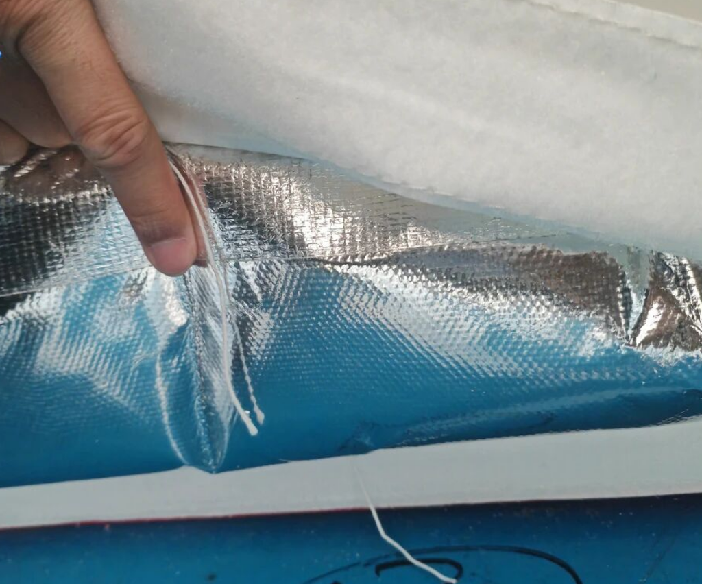
A lower heat transfer coefficient indicates less heat loss and, consequently, superior thermal insulation performance.
Taking a venue with a projected building area of 1,000 m² as an example—assuming a target constant indoor temperature of 18°C during winter and an outdoor design temperature for heating calculations of -12°C—the temperature differential between the interior and exterior is 30°C.
With the addition of insulation (glass wool), heat loss through the membrane structure is reduced by more than half, leading to an overall decrease in heating energy consumption of approximately 30%–45%.